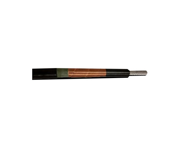
High Voltage Shielded Cable
Product Details:
overall diameter Approx 36 mm
Withsatnd Voltage 500KV
Impedence 18 Ohm
Capcitance 285pF/m
Inductance 93nH/m
HVSC Plus is a concentric conductor designed with special features to handle lightning transients. The key features of the design can be summarised as follows: Use of a cylindrical filler material to produce an “annular†design for the inner conductor. This design is optimised for carrying high-frequency or transient currents, namely lower inductance and allowance for the “Skin effectâ€. Furthermore, the cross-sectional area of the inner conductor is large enough to be completely compliant with all international standards for lightning protection [1-4]; An insulation layer of sufficient thickness to withstand voltages of a pre-specified level, surrounded by thin semiconductive “stress-control†layers applied during a “triple extrusion†manufacturing process; A conductive, copper-tape outer screen layer that provides screening of electric fields; A rugged PVC outer sheath or jacket to protect the cable during installation and in-service period; Performance independent of the type of structure on which it is installed, e.g., metallic, masonry, non-conductive, etc.
The voltage within the cable is divided across two known geometries, namely between the inner conductor and the screen, and between the screen and the structure. These voltages are controlled through knowledge of the main cable parameters, viz., impedance, inductance, capacitance and phase velocity. The HVSC Plus cable design is shown in Figure 1. From the inside to the outside, the components are as follows:
(i) Solid, cylindrical, polyethylene filler;
(ii) Inner conductor comprised of copper strands (XSA 70 mm2); (iii) Binder tape;
(iv) Semiconductive stress-relief layer (“conductor screenâ€)
(v) Polyethylene insulation (approx. 5 mm thick);
(vi) Semiconductive stress-relief layer (“insulation screenâ€)
(vii) Copper tape main screen;
(viii) PVC outer sheath.
The cable has an overall diameter of approximately 36 mm. The typical installation practice for the cable can be summarised as follows. The cable must be: Correctly terminated at the upper end – specific cut lengths of the various layers and then the application of a high-voltage termination kit (see installation guide); Electrically shorted (inner-to-screen connection) at the bottom end and bonded to the base of the structure; Installed in such a way as to not infringe on the minimum bend radius criterion.
